Traditional linear (±) tolerancing controls only nominal dimensions—ignoring how features relate in space. GD&T, by contrast, uses standardized geometric symbols to manage form, orientation, and location relative to functional datums—ensuring casting parts perform as intended in final assemblies. Flatness tolerance directly limits warping on mounting surfaces, preventing gasket compression failure due to uneven contact. Positional tolerance defines cylindrical zones around hole centers, maintaining bolt alignment even with localized variation—unachievable with linear tolerancing’s rigid rectangular envelopes. Coaxiality ensures rotational axes remain aligned despite minor bending or runout, preserving kinematic function in rotating components like hydraulic pump drives. This targeted control allows relaxed dimensional specs elsewhere without sacrificing performance.
Linear tolerancing assumes worst-case additive error across every dimension—a statistically improbable scenario that forces over-engineering. In multi-part casting assemblies, this approach compounds variation unnecessarily. GD&T mitigates stack-up through functional datum referencing and statistical tolerance analysis. For example, positional tolerance for bolt-hole patterns accommodates natural variation within a cylindrical zone, preventing misassembly while avoiding the “bubble-tight” ±0.25mm constraints that linear specs impose. When applied to precision applications like pump housings requiring wavefront alignment, GD&T’s profile tolerances govern entire surface relationships—not just endpoints—ensuring shape integrity where it matters most.
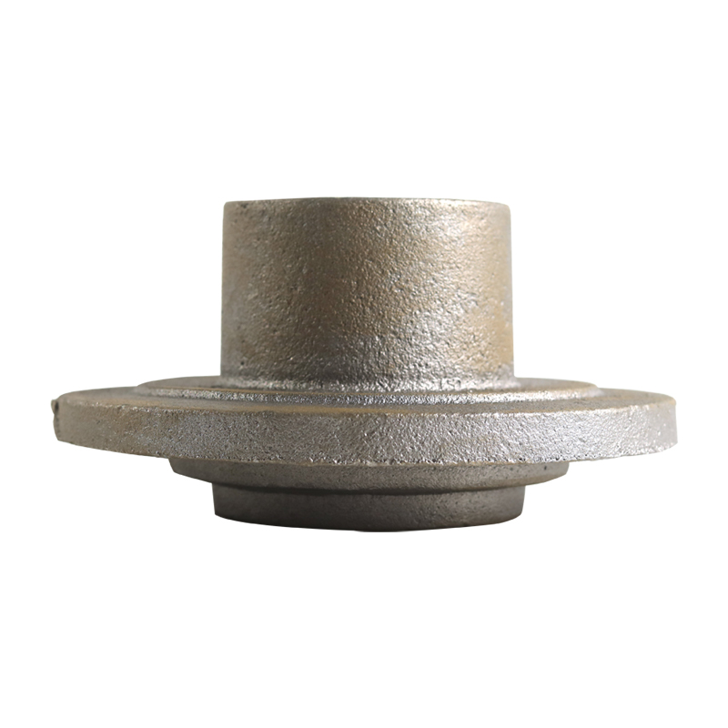
Tightening tolerance classes beyond CT5–CT6 triggers disproportionate cost escalation. Per NADCA and ISO 8062-3 benchmarks, each grade tighter than CT6 increases per-unit cost by 40–60%—driven by extended cycle times, specialized tooling, and higher rejection rates. Moving from CT6 to CT4 commonly doubles tooling investment and triples lead times for secondary machining. Crucially, the physics of casting imposes hard limits: alloy shrinkage, mold thermal gradients, and die wear inherently constrain achievable accuracy below CT5. Specifying tighter tolerances rarely improves functional performance but consistently inflates cost—making CT5–CT6 the practical ceiling for most production castings.
Over-specification also incurs four major hidden costs. First, rework incidence jumps to 15–25% for features tighter than CT6—versus under 5% for standard CT7–CT8 parts. Second, scrap rates exceed 10% when critical features push process capability. Third, inspection overhead surges: programming CMMs, validating measurement routines, and completing first-article approvals often adds two to four weeks per order. Fourth, supplier qualification narrows significantly—fewer than 40% of qualified foundries accept sub-CT5 requirements, shrinking the vendor pool and weakening procurement leverage. Collectively, these factors can inflate total cost of ownership by 30–50%, delivering no functional benefit to the casting parts.
Three interrelated physical phenomena drive dimensional variation in casting parts. Alloy shrinkage—ranging from 1% to 3% depending on composition—creates predictable but often underestimated deviations during solidification. Mold thermal gradients cause non-uniform cooling: thin sections solidify faster than thick ones, inducing warpage, bending, or twisting. Die and tooling wear accumulates over production cycles, gradually enlarging cavity dimensions and worsening parting-line mismatch. These effects intensify with design complexity—abrupt wall transitions or asymmetrical geometries amplify distortion. Without proactive thermal modeling and disciplined tool maintenance, cumulative variation routinely exceeds tolerance bands, triggering rework or scrap.
Casting Tolerance (CT) grades—from coarse CT9 to precise CT5—reflect realistic process capability, not arbitrary precision targets. ISO 8062 defines these bands as percentage-based allowances tied to part dimensions and geometry. For example, CT7 permits ±0.35% variation for castings under 300 mm. Key variables shaping CT selection include:
Shrinkage behavior further informs selection—steel castings add roughly ±0.1% shrinkage variation per CT grade step between CT6 and CT8. Designers should prioritize CT ratings aligned with functional requirements—not perceived “precision”—and partner with foundries using thermal simulation to predict and compensate for dimensional shifts before tooling is cut.
Q: What is the primary advantage of GD&T over linear tolerancing for casting parts?
A: GD&T allows for more precise control of the geometric relationships between features, aligning with functional needs while avoiding unnecessary over-specification in other areas.
Q: Why does over-specifying tolerances on casting parts lead to excessive costs?
A: Tight tolerances increase costs through extended cycle times, expensive tooling, higher rejection rates, inspection overheads, and limited supplier availability.
Q: How do physical phenomena like alloy shrinkage affect casting tolerances?
A: Alloy shrinkage, thermal gradients, and tooling wear cause dimensional changes during production, requiring proactive measures like thermal modeling to minimize variation.
Q: What is the practical tolerance range for most production castings?
A: CT5 to CT6 is considered optimal for most castings as tighter tolerances rarely improve functionality and substantially increase costs.
Q: How do CT grades relate to casting dimensions and geometry?
A: CT grades define tolerance allowances as percentages of part size, with complexity, size, and wall thickness influencing the appropriate grade.

 EN
EN